06 Stand simulation verification
6.1 Overall simulation verification of the bracket
In order to verify the overall stability and bearing capacity of the bracket, the bracket was simulated by ABAQUS finite element software. According to the Code for Building Structural Loads and the Design Code for Photovoltaic Power Stations, taking the Zhengzhou project in Henan Province as an example, the basic wind pressure in the area in 25 years is 0.38kn/m2, and the adjusted wind pressure value is 0.72kn/m2 through article 4.1 of this article. It is applied to the bracket system by means of a surface load. Fig. 11 and Fig. 12 show the overall simulation results of rack and row rack brackets, respectively, and the results show that the maximum displacement of the structural beam generated by wind pressure is about 0.19mm and 0.49mm, respectively, which is less than 1/250 of the calculated span of the beam, which meets the "Design Code for Photovoltaic Power Stations" (GB50797-2012). The lateral movement of the column side caused by the wind pressure is 0.1mm and 0.36mm, respectively, which is less than 1/60 of the column height, which also meets the requirements of the specification. Therefore, the overall stability of the structure meets the requirements.
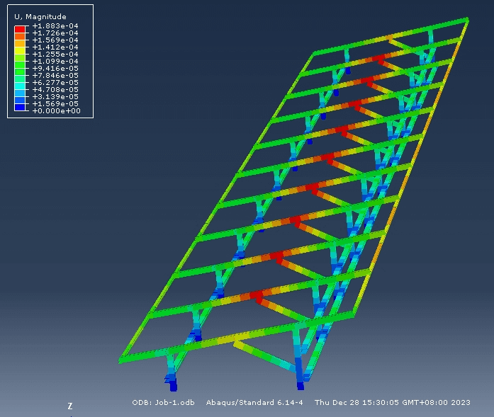
Fig.11 Stability analysis of rack brackets
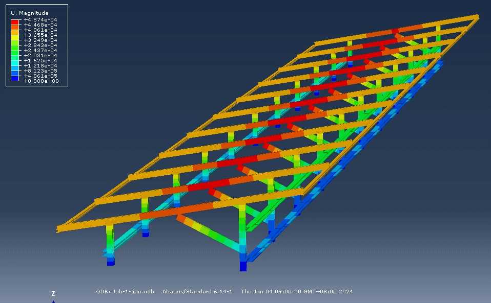
Fig.12 Stability analysis of row-rack brackets
It should be pointed out that the structure of the row rack bracket has more constraints and a higher number of superstatic fixations than the row frame bracket, so the structural displacement is small and the stability is good. From the perspective of structural stability, this paper recommends the use of rack-type bracket structure system.
6.2 Simulation verification of briquetting and beam joints
In order to verify the force on the briquetting block and the beam joint, a beam is simulated and analyzed by using a three-dimensional stress unit. The wind load is applied to the briquette, through which it is transmitted to the beam, and a fixed support is set at the bottom of the triangular connector, see Figure 13, and the beam is fixed by the triangular support.
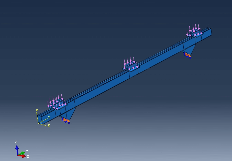
Fig.13 Wind pressure application diagram
The design specification requires that the bolts used in the bracket are fixed and tightened. Therefore, the parts can be regarded as tightly combined without slippage, and the co-unit node is used for simulation analysis. It can be seen from Fig. 14 and Fig. 15 that the maximum stress generated by wind pressure is 160.2MPA on the beam, which is less than the design value of steel strength of 215MPA.
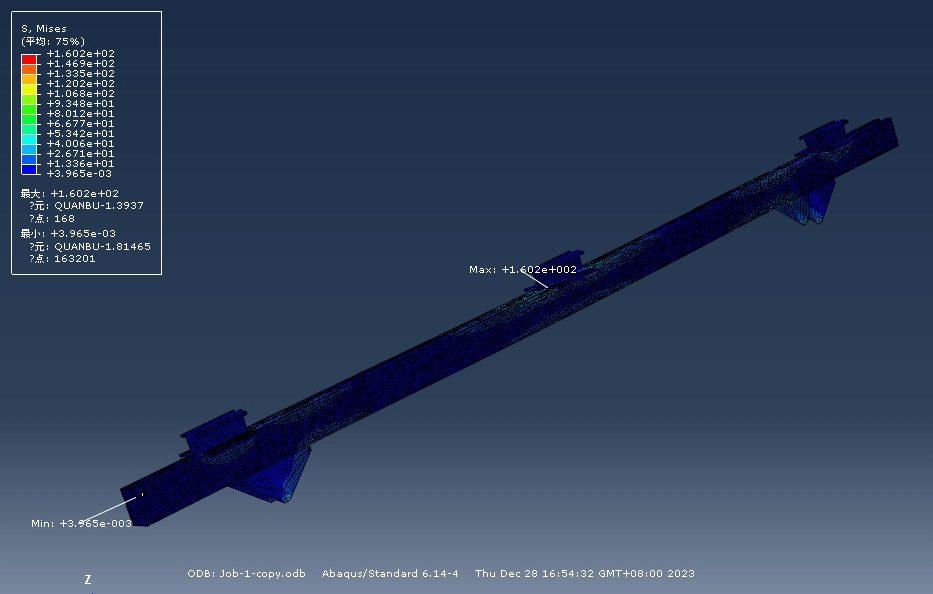
Fig.14 Overall simulation results
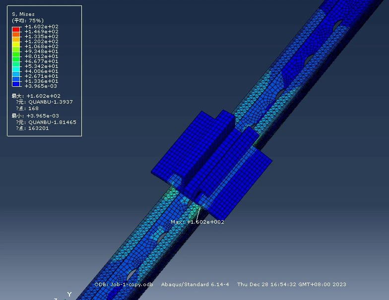
Fig.15 Stress diagram generated by wind pressure
It can be seen from Fig. 16 that the maximum displacement generated by wind pressure is 0.95mm (especially pointing out that this displacement is different from the displacement shown in Fig. 11 and 12, because the load application method is different, Fig. 11 and Fig. 12 are only to verify the overall stability of the structural system, so the load adopts the method of applying line load along the beam), and the cross-section of the beam has no warping, so the innovative briquetting joint meets the strength requirements.
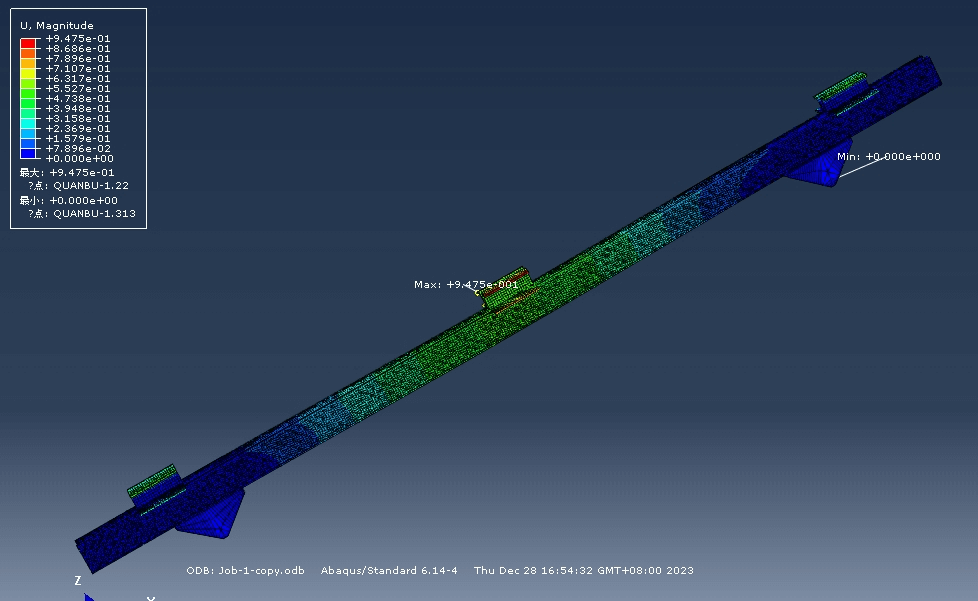
Fig.16 Displacement diagram generated by wind pressure
Fig. 17 and Fig. 18 show the displacement and stress diagram of the node and the beam under the action of wind suction. The maximum displacement occurs on the briquette of 0.58mm, and the maximum stress occurs on the beam at 96MPA, which is also less than the design value of steel strength of 215MPA. Therefore, under the action of wind suction, the nodes and beams also meet the strength requirements.
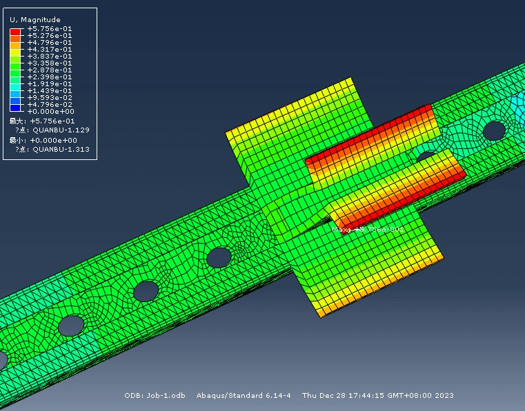
Fig.17 Displacement diagram generated by wind suction
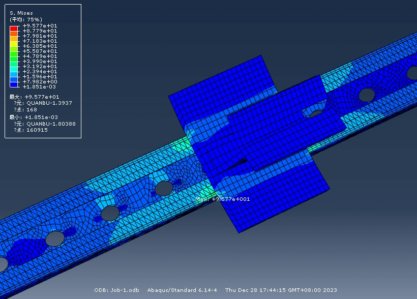
Fig.18 Stress diagram generated by wind suction
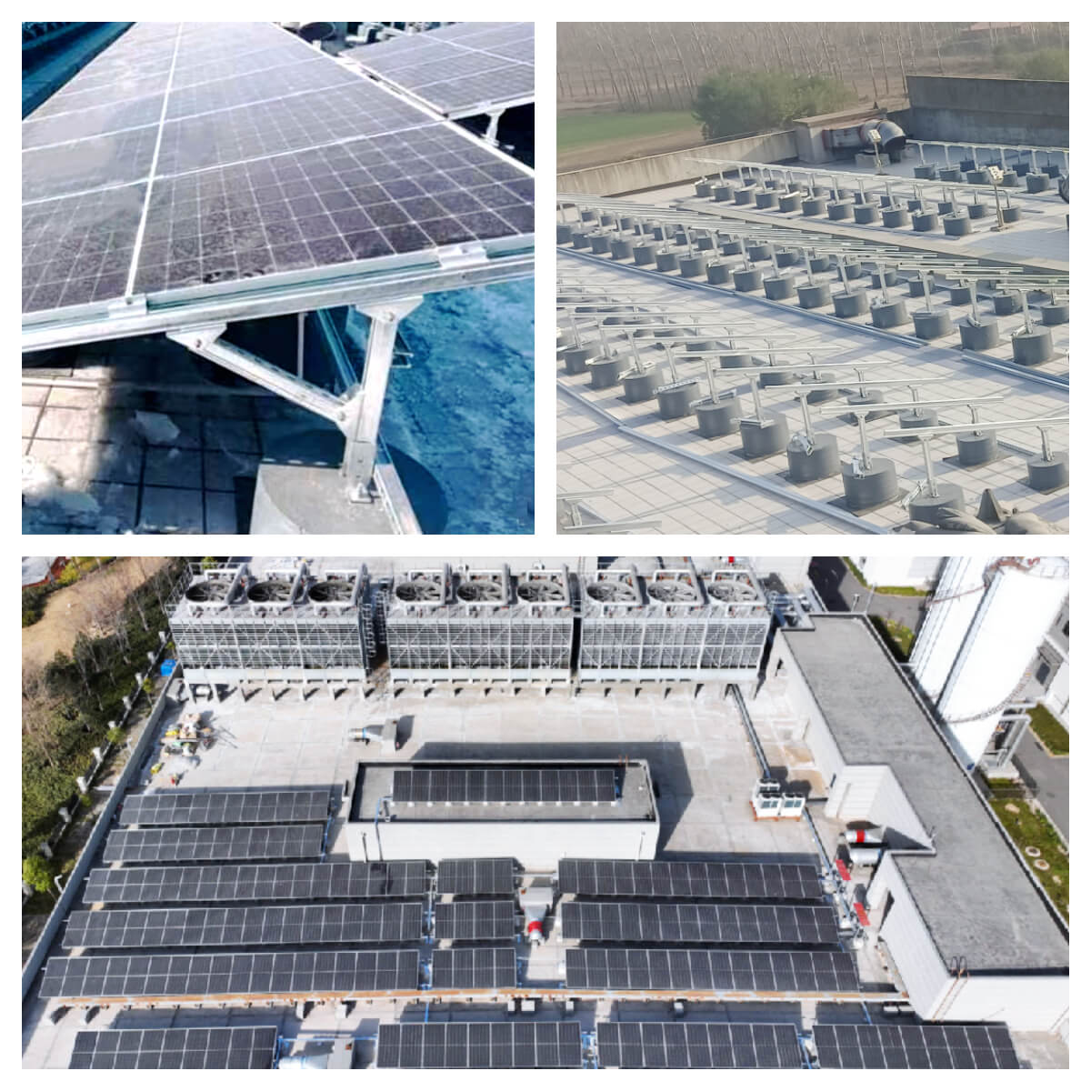
07 Application Cases
This innovative solution uses common materials and strong applicability by eliminating the purlins of the photovoltaic bracket, placing the double-sided module brackets on the beams, and then setting up longitudinal supports on the front and rear columns. Through the actual engineering inspection, good results have been achieved. See the attached picture below.