


01 Introduction
With the rapid development of science and technology and the improvement of people's awareness of environmental protection, renewable energy has received more and more attention. Among them, photovoltaic power generation, as a clean renewable energy, is being widely used. Solar cells are the core part of the photovoltaic power generation system, and the most used solar cell modules on the market are single-sided modules, that is, the modules only support solar power generation. With the advancement of technology, bifacial battery modules that can generate electricity on both sides have also been more used. It is estimated that bifacial modules can increase power generation by 10%~30%. Moreover, bifacial modules can reduce shadow effects in photovoltaic systems, improving system reliability and stability. However, the "purlin + beam" bracket system used in traditional single-sided modules will cause obstruction to the back of double-sided modules, which is not conducive to improving the power generation efficiency of double-sided modules.
Therefore, this paper proposes a new form of bifacial module bracket structure according to the characteristics of bifacial modules, which adopts common photovoltaic brackets, which have the advantages of easy installation and low cost, and can be used as a reference for distributed photovoltaic power generation projects.
02 Traditional component brackets
For single-sided photovoltaic modules, the commonly used bracket method is shown in Figure 1.
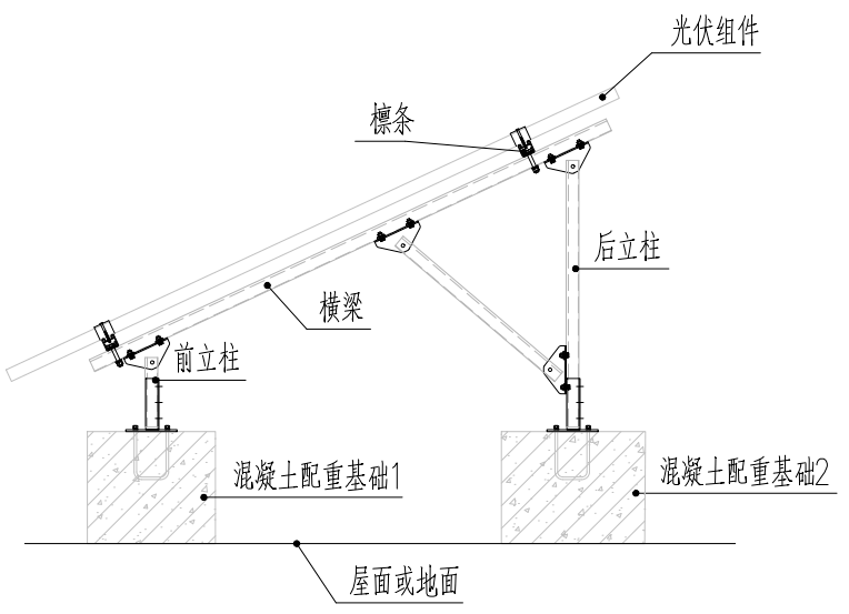
The bracket system is supported by two columns in the front and back, and purlins are erected along the beam longitudinally, and the components are fixed by briquettes on the purlins. The system is fixed on the roof or ground by concrete counterweight piers of the front and rear columns. The structure is formed by diagonal braces in the horizontal direction, and the fixed system is formed by concrete foundations and purlins in the vertical direction. After many practical projects, the structural system can meet the structural safety needs of photovoltaic use.
03 Characteristics of bifacial photovoltaic modules
Single-sided PV modules have PN junctions on only one side, so they can only absorb solar energy from one side. while bifacial photovoltaic modules have PN junctions on both sides, which can absorb solar energy from both sides at the same time. Therefore, the bracket purlins of bifacial photovoltaic modules should be located at the edge of the modules, otherwise the longitudinal purlins of the brackets will cause obstruction to the back of the bifacial modules, greatly reducing the power generation advantages of bifacial modules. At the same time, other electrical equipment (such as string inverters) should be avoided as much as possible from obstructing the back of the module.
04 Load of double-sided photovoltaic bracket
4.1 Wind loads
When designing photovoltaic brackets, the basic wind pressure is determined according to the 25-year return period; When designing the foundation, the basic wind pressure is determined according to the 50-year return period, and the safety factor of 1.6 is considered. The standard value of wind load acting vertically on the surface of the photovoltaic bracket structure or photovoltaic module can be calculated as follows:
Where:
wk - standard value of wind load (kn/m2);
βz—wind vibration coefficient at height z;
us, uz - wind load carrier type coefficient, wind load height coefficient;
w0 – local basic wind pressure (kn/m2).
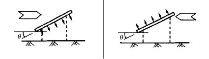
In addition to the lateral wind load, the horizontal force generated by the longitudinal wind load on the support should also be considered. When calculating wind pressure, attention should be paid to the directionality of wind load, as shown in Figure 2.
4.2 Snow load
The snow load acting on the horizontal projection surface of the photovoltaic bracket has a return period of 25 years. When the foundation is designed, the snow load is determined according to the 50-year return period. For photovoltaic modules installed on the roof of buildings, the uneven distribution coefficient of snow caused by windward side, leeward side, obstruction, etc. should be considered.
4.3 Load combination
When designing the photovoltaic bracket structure, the limit state of bearing capacity and the limit state of normal use should be calculated. The former mainly calculates the strength, stability and connection strength of the supporting components; The latter mainly calculates the deformation, cracks, etc. of the bracket. The load effect calculation is divided into two working conditions, namely seismic calculation and non-seismic calculation.
In the non-seismic calculation, the basic combination of load effects is calculated as follows:
Where:
Sd - the effect design value of the load combination;
γG - the sub-coefficient of permanent load, take 1.3;
γW, γS—the sub-coefficients of wind load and snow load, take 1.5;
SGK, SWK, SSK - permanent load standard value effect, wind load standard value effect, snow load standard value effect;
ΨW, ΨS—the combined value coefficient of wind load and snow load, when wind load or snow load is the dominant load, the combined coefficient is taken as 1.0;
When seismic calculation, the basic combination of load effects is calculated as follows:
Where:
Sd - the effect design value of the seismic combination;
γG, γE, γW—the sub-coefficient of gravity load is 1.3, the sub-coefficient of horizontal seismic action is 1.3, and the sub-coefficient of wind load is 1.5;
SGE, SEhK - the effect of the representative value of gravity load and the effect of the standard value of horizontal seismic action;
ΨW - the combined value coefficient of wind load, when the wind load plays a controlling role, take 0.2, otherwise take 0.0;


