Data center hierarchy
The construction scale and requirements of various types of data centers vary greatly, so the data center should confirm the level requirements of the data center of the project with the owner before construction.
According to the Data Center Design Code (GB50174-2017), data centers are mainly divided into three levels: A, B, and C:
During operation, the site equipment should not be interrupted due to operation errors, equipment failures, external power supply interruptions, maintenance and overhaul.
The B-level electronic information system computer room should be set up in accordance with the redundancy requirements, and the site equipment should not cause the electronic information system to operate due to equipment failure within the redundancy capacity.
The C-level electronic information system computer room should be configured according to basic needs to ensure that the operation of the electronic information system is not interrupted.
Data center location and overall planning
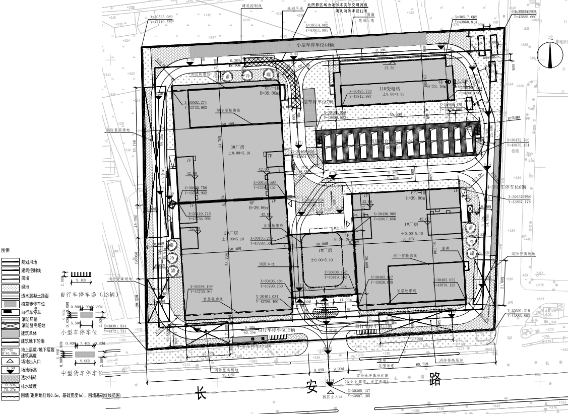
3.1 Data center site selection
The specific demand area should be considered first, and it should be as close as possible to the main application city, and at the same time, issues such as electricity, communication, transportation, water sources, and natural environment should be considered:
3.1.1 Electricity
The electricity consumption of data centers is generally relatively large, and the power supply and stability of electricity consumption in construction sites should be examined.
3.1.2 Communications
Data centers should be close to core network nodes to reduce network latency;
3.1.3 Transportation
There are as many roads as possible and smooth to meet the needs of timely support;
3.1.4 Water source
The water consumption of water evaporation and heat dissipation per kilowatt of IT equipment per day is about 100L, as follows: circulating cooling water (m³/h) = IT load (KW) x (0.25~0.30), and the hourly water replenishment is: circulating water (m³/h). x1.4%, a day is 24h; For example: 6000kw IT equipment, the daily water consumption is: 6000x0.25x0.014x24=504 tons, and the annual need is 504x365=183960 tons, therefore, the water source of the refrigeration data center using water evaporative cooling should be sufficient;
3.1.5 Natural environment
The construction of data centers in different regions will cause different costs due to different indicators such as ambient temperature and air cleanliness, and the choice of areas that are as conducive to energy conservation as possible will be selected.
3.2 General plan planning
For the selected construction land plots, the main content design should be mainly considered when meeting the planning technical conditions:
3.2.1 Vertical design
The absolute elevation of the first floor of the newly built A-level data center should be more than 1.0m higher than the water level line of the local flood century-old return period, and should be more than 0.6m higher than the outdoor floor, and should be higher than the absolute elevation of the surrounding roads to prevent waterlogging.
3.2.2 Phased planning
The general data center is divided into civil construction stage and mechanical and electrical stage, and the owner will generally implement it in stages in order to control the investment to adapt to the capital needs and customer changing needs. The civil development stage is mainly declared as a large open Class C workshop, and after completion and acceptance, mechanical and electrical construction is carried out, which may involve demolition and structural reinforcement for large changes in customer demand.
3.3 Building layout
The layout of each building in the general plan should also consider the fire spacing requirements, fire lane layout, diesel steel platform, cold storage tank layout, oil storage tank location, sunlight on surrounding plots, noise impact, truck transportation path and turning radius loading and unloading operation distance, rainwater collection pond, underground pipe ditch location, etc.