With the rapid development of science and technology and the improvement of people's awareness of environmental protection, renewable energy has received more and more attention. Among them, photovoltaic power generation, as a clean renewable energy, is being widely used. Solar cells are the core part of the photovoltaic power generation system, and the most used solar cell modules on the market are single-sided modules, that is, the modules only support solar power generation. With the advancement of technology, bifacial battery modules that can generate electricity on both sides have also been more used. It is estimated that bifacial modules can increase power generation by 10%~30%. Moreover, bifacial modules can reduce shadow effects in photovoltaic systems, improving system reliability and stability. However, the "purlin + beam" bracket system used in traditional single-sided modules will cause obstruction to the back of double-sided modules, which is not conducive to improving the power generation efficiency of double-sided modules.
Therefore, this paper proposes a new form of bifacial module bracket structure according to the characteristics of bifacial modules, which adopts common photovoltaic brackets, which have the advantages of easy installation and low cost, and can be used as a reference for distributed photovoltaic power generation projects.
对于单面光伏组件,常用的支架方式如图1所示。 For single-sided photovoltaic modules, the commonly used bracket method is shown in Figure 1.
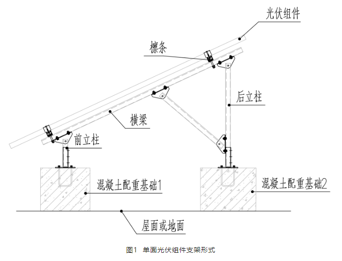
The bracket system is supported by two columns in the front and back, and purlins are erected along the beam longitudinally, and the components are fixed by briquettes on the purlins. The system is fixed on the roof or ground by concrete counterweight piers of the front and rear columns. The structure is formed by diagonal braces in the horizontal direction, and the fixed system is formed by concrete foundations and purlins in the vertical direction. After many practical projects, the structural system can meet the structural safety needs of photovoltaic use.
Single-sided PV modules have PN junctions on only one side, so they can only absorb solar energy from one side. while bifacial photovoltaic modules have PN junctions on both sides, which can absorb solar energy from both sides at the same time. Therefore, the bracket purlins of bifacial photovoltaic modules should be located at the edge of the modules, otherwise the longitudinal purlins of the brackets will cause obstruction to the back of the bifacial modules, greatly reducing the power generation advantages of bifacial modules. At the same time, other electrical equipment (such as string inverters) should be avoided as much as possible from obstructing the back of the module.
When designing photovoltaic brackets, the basic wind pressure is determined according to the 25-year return period; When designing the foundation, the basic wind pressure is determined according to the 50-year return period, and the safety factor of 1.6 is considered. The standard value of wind load acting vertically on the surface of the photovoltaic bracket structure or photovoltaic module can be calculated as follows:
wk=βzusuzw0
Where:
wk - standard value of wind load (kn/m2);
βz—wind vibration coefficient at height z;
us, uz - wind load carrier type coefficient, wind load height coefficient;
w0 – local basic wind pressure (kn/m2).
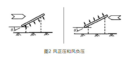
In addition to the lateral wind load, the horizontal force generated by the longitudinal wind load on the support should also be considered. When calculating wind pressure, attention should be paid to the directionality of wind load, as shown in Figure 2.
4.2 Snow load
The snow load acting on the horizontal projection surface of the photovoltaic bracket has a return period of 25 years. When the foundation is designed, the snow load is determined according to the 50-year return period. For photovoltaic modules installed on the roof of buildings, the uneven distribution coefficient of snow caused by windward side, leeward side, obstruction, etc. should be considered.
4.3 Load combination
When designing the photovoltaic bracket structure, the limit state of bearing capacity and the limit state of normal use should be calculated. The former mainly calculates the strength, stability and connection strength of the supporting components; The latter mainly calculates the deformation, cracks, etc. of the bracket. The load effect calculation is divided into two working conditions, namely seismic calculation and non-seismic calculation.
● When calculating non-seismic resistance, the basic combination of load effects is calculated as follows:
Where:
Sd - the effect design value of the load combination;
γG - the sub-coefficient of permanent load, take 1.3;
γW, γS—the sub-coefficients of wind load and snow load, take 1.5;
SGK, SWK, SSK - permanent load standard value effect, wind load standard value effect, snow load standard value effect;
ΨW, ΨS—the combined value coefficient of wind load and snow load, when wind load or snow load is the dominant load, the combined coefficient is taken as 1.0;
● When seismic resistance is calculated, the basic combination of load effects is calculated as follows:
Where:
Sd - the effect design value of the seismic combination;
γG, γE, γW—the sub-coefficient of gravity load is 1.3, the sub-coefficient of horizontal seismic action is 1.3, and the sub-coefficient of wind load is 1.5;
SGE, SEhK - the effect of the representative value of gravity load and the effect of the standard value of horizontal seismic action;
ΨW - the combined value coefficient of wind load, when the wind load plays a controlling role, take 0.2, otherwise take 0.0;
5.1 Lateral structure system of brackets
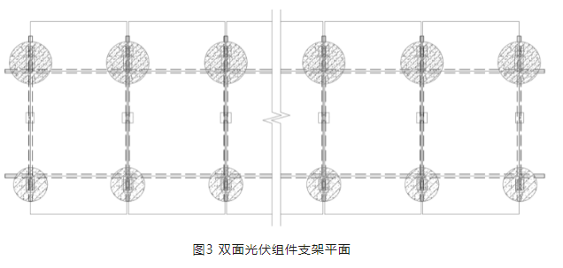
Since there should be no occlusion behind the double-sided photovoltaic module, the double-sided photovoltaic module is not suitable for the structural system of column "beam + purlin". Therefore, the purlins can be canceled and the photovoltaic modules can be directly connected to the beams on both sides, as shown in Figure 3.
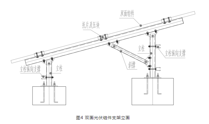
Beams are set on both sides of each photovoltaic module, and the modules are fixed to the beams by briquettes and pallets, and the beams are fixed to the foundation by front and rear columns. In order to ensure the lateral stability of the structure, one longitudinal support is provided along the longitudinal direction of the front column, and two longitudinal supports are set along the longitudinal direction of the rear column, and the façade of the double-sided photovoltaic module bracket is shown in Figure 4. The bracket structure system eliminates the longitudinal purlins, which effectively avoids its occlusion to the back of the module. At the same time, the longitudinal support set by the column provides the longitudinal stiffness of the bracket, so that the bracket forms a stable bracket system in the longitudinal direction. For specific installation effects, please refer to the application case in Section 7.
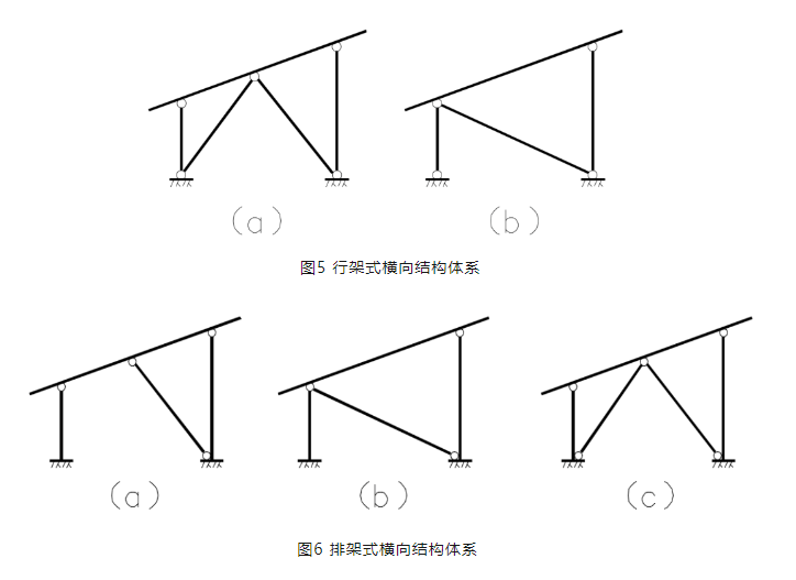
The transverse structure of the support shown in Figure 4 can be divided into two structural systems according to the different forms of connection between the column and the foundation, the form of column bottom hinge and column bottom consolidation. The hinge form of the column bottom is a row-type horizontal structure system, and the column bottom is consolidated into a row-type horizontal structure system. The two forms shown in Fig. 5 are row-frame transverse structure systems, in which the front and rear columns and foundations are hinged, and one or two transverse supports are used to provide lateral stiffness to form a stable structural unchanging system. The three forms shown in Fig. 6 are all rack-type transverse structure systems, in which the front and rear columns and foundations are consolidated, and one or two longitudinal supports are used to provide lateral stiffness and enhance the stability of the structure. The basic design is the same as that of traditional photovoltaic brackets.
5.2 Longitudinal structure system of the bracket
The longitudinal structure system of the support is also divided into two structural systems according to the different forms of connection between the column and the foundation, the form of column bottom hinge and column bottom consolidation. The articulation form of the column bottom is a row-type longitudinal structure system, see Fig. 7. The column bottom is consolidated into a rack-type longitudinal structure system, see Fig. 8.
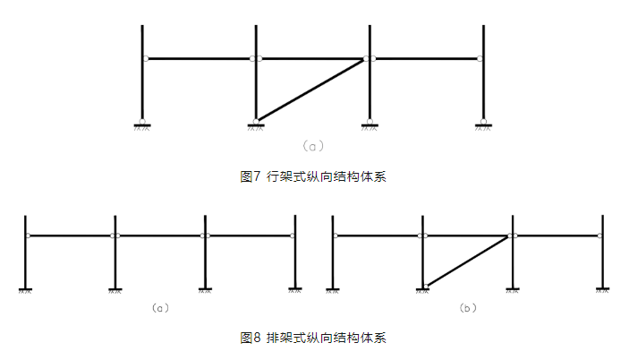
It can be seen from Fig. 7 that due to the articulation of the column bottom, the longitudinal diagonal brace must be set up in the vertical direction of the column to ensure that the longitudinal direction of the bracket forms a stable structural system. For the rack type longitudinal structure system, because the bottom of the column is fixed, the longitudinal support is determined according to the actual stress situation. Regardless of whether it is a row-type or a row-type bracket system, the longitudinal horizontal support is set on the column, and there is a certain distance from the back of the module, which can effectively avoid the obstruction of the double-sided photovoltaic module by the rods, so as to better give full play to the advantages of the double-sided module and increase the power generation.
5.3 Bracket material
The advantage of this innovative bracket solution is that it can use conventional photovoltaic bracket members and materials, and has a wide range of applicability. The commonly used members are shown in Figure 9.
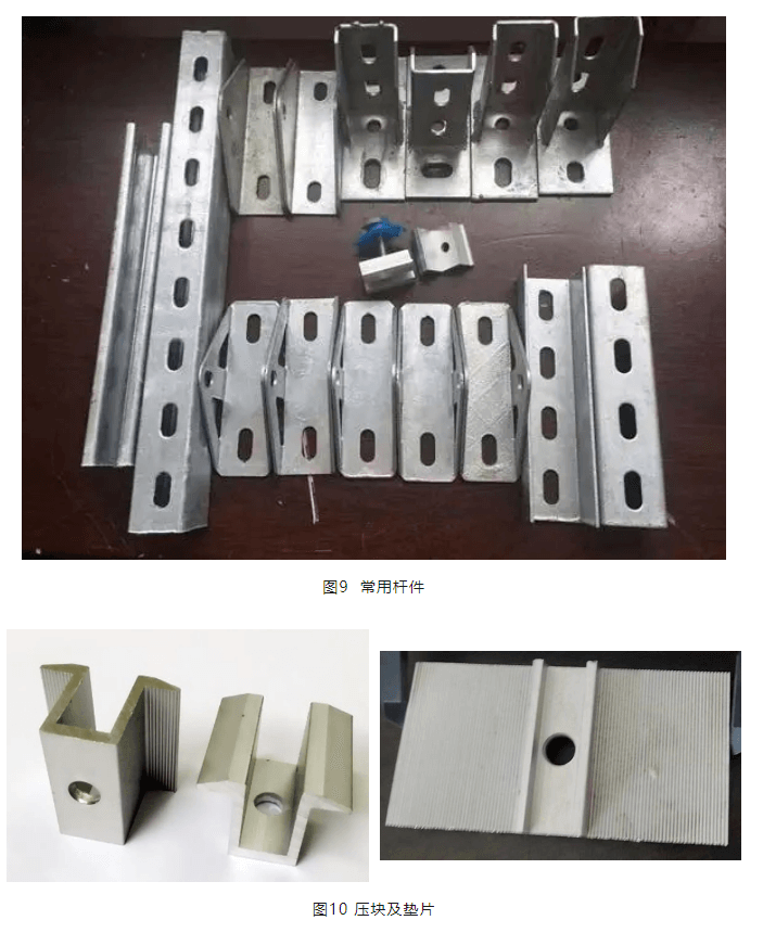
Figure 10 shows the commonly used briquettes and gaskets of photovoltaics, which are tightened with bolts and fixed with photovoltaic modules in the middle.
6.1 Overall simulation verification of the bracket
In order to verify the overall stability and bearing capacity of the bracket, the bracket was simulated by ABAQUS finite element software. According to the Code for Building Structural Loads and the Design Code for Photovoltaic Power Stations, taking the Zhengzhou project in Henan Province as an example, the basic wind pressure in the area in 25 years is 0.38kn/m2, and the adjusted wind pressure value is 0.72kn/m2 through article 4.1 of this article. It is applied to the bracket system by means of a surface load. Fig. 11 and Fig. 12 show the overall simulation results of rack and row rack brackets, respectively, and the results show that the maximum displacement of the structural beam generated by wind pressure is about 0.19mm and 0.49mm, respectively, which is less than 1/250 of the calculated span of the beam, which meets the "Design Code for Photovoltaic Power Stations" (GB50797-2012). The lateral movement of the column side caused by the wind pressure is 0.1mm and 0.36mm, respectively, which is less than 1/60 of the column height, which also meets the requirements of the specification. Therefore, the overall stability of the structure meets the requirements.
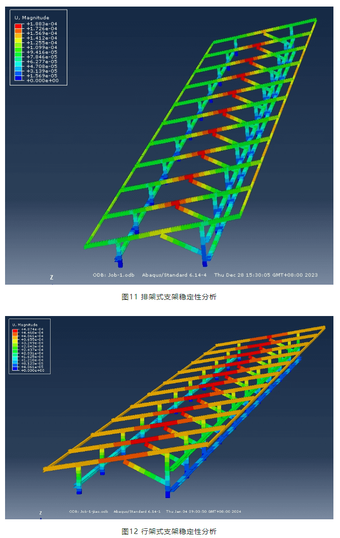
It should be pointed out that the structure of the row rack bracket has more constraints and a higher number of superstatic fixations than the row frame bracket, so the structural displacement is small and the stability is good. From the perspective of structural stability, this paper recommends the use of rack-type bracket structure system.
6.2 Simulation verification of briquetting and beam joints
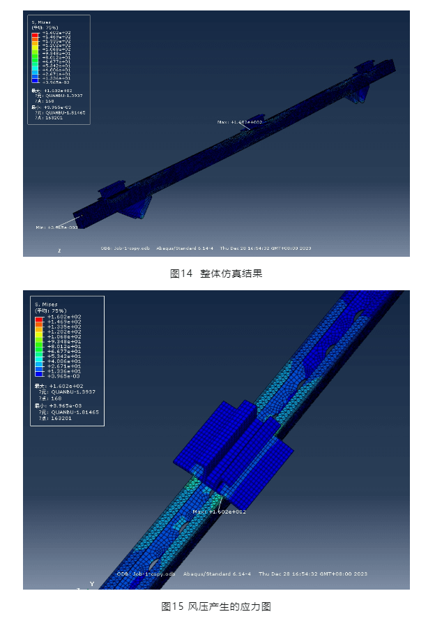
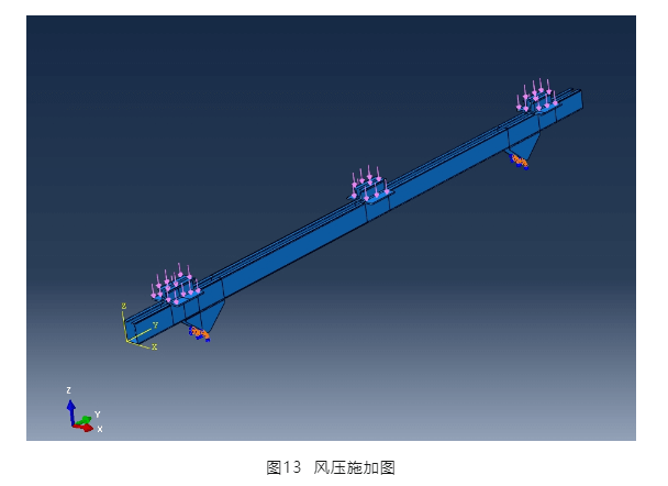
In order to verify the force on the briquetting block and the beam joint, a beam is simulated and analyzed by using a three-dimensional stress unit. The wind load is applied to the briquette, through which it is transmitted to the beam, and a fixed support is set at the bottom of the triangular connector, see Figure 13, and the beam is fixed by the triangular support.
The design specification requires that the bolts used in the bracket are fixed and tightened. Therefore, the parts can be regarded as tightly combined without slippage, and the co-unit node is used for simulation analysis. It can be seen from Fig. 14 and Fig. 15 that the maximum stress generated by wind pressure is 160.2MPA on the beam, which is less than the design value of steel strength of 215MPA.
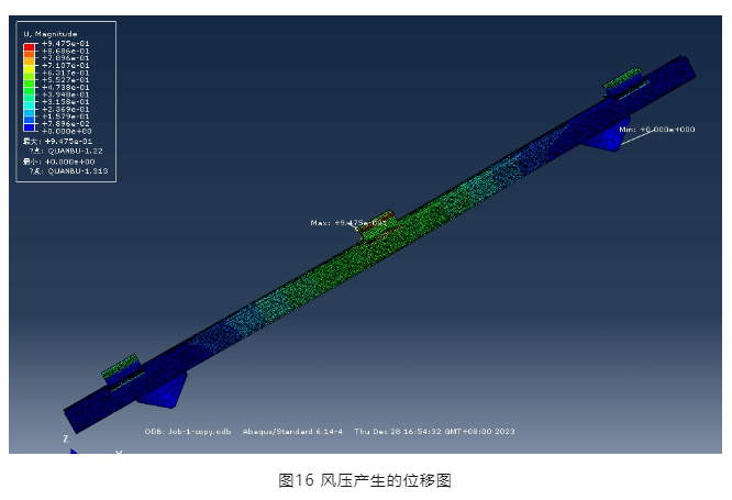
It can be seen from Fig. 16 that the maximum displacement generated by wind pressure is 0.95mm (especially pointing out that this displacement is different from the displacement shown in Fig. 11 and 12, because the load application method is different, Fig. 11 and Fig. 12 are only to verify the overall stability of the structural system, so the load adopts the method of applying line load along the beam), and the cross-section of the beam has no warping, so the innovative briquetting joint meets the strength requirements.
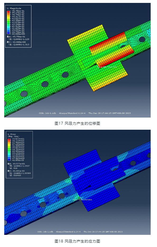
Fig. 17 and Fig. 18 show the displacement and stress diagram of the node and the beam under the action of wind suction. The maximum displacement occurs on the briquette of 0.58mm, and the maximum stress occurs on the beam at 96MPA, which is also less than the design value of steel strength of 215MPA. Therefore, under the action of wind suction, the nodes and beams also meet the strength requirements.
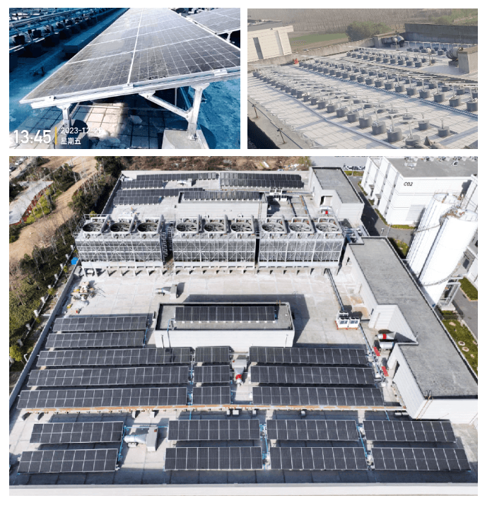
This innovative solution uses common materials and strong applicability by eliminating the purlins of the photovoltaic bracket, placing the double-sided module brackets on the beams, and then setting up longitudinal supports on the front and rear columns. Through the actual engineering inspection, good results have been achieved. See the attached picture below.