


With the explosive growth of Internet and cloud computing demand, the scale of data centers continues to expand, and problems such as stability, energy consumption, and land occupancy continue to plague data center operators, and new problems such as maintenance and continuous expansion have followed. To meet the challenges, the form of data centers is constantly changing. From the early centralized power supply centralized cooling to distributed power supply distributed cooling, from the simple adjustment of the cabinet placement direction to the closed cool/hot aisle, from the data center with simple division of functional zones to the popular micro-module data center now. Today, let's understand the importance of data center routine O&M and familiarize yourself with the work content of data center routine O&M through the following.
1. The importance of routine operation and maintenance work
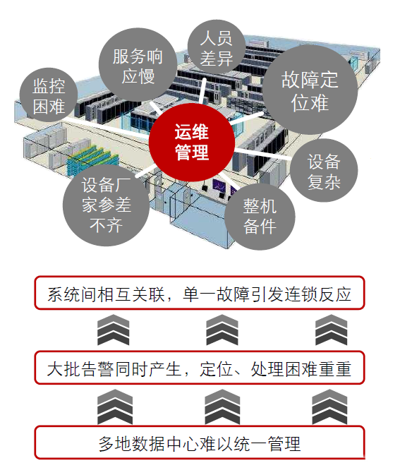
Challenges faced by operations and maintenance work
-
The higher the power density, the shorter the response time for operation and maintenance personnel, and the more difficult to manage.
-
The Uptime report shows that more than 70% of data center failures are caused by human error.
1. Main fault types:
1. Caused by wear and tear
-
The equipment also has a life phenomenon, after reaching a certain degree of use, it will die, and it will not be repaired, only upgrading, which is most obvious in high-precision equipment.
-
The wear of equipment can be divided into two types: tangible wear and intangible wear. Tangible wear refers to the material wear and tear that occurs during the use of equipment or physical and chemical changes caused by natural environmental erosion. Invisible wear refers to the fact that due to the progress of science and technology, the use value of equipment is reduced or even eliminated.
2. Abnormal operation
-
Almost all equipment has strict requirements for the action sequence, and if you do not follow the operating procedures, it will only directly lead to or accelerate its failure. In on-site management activities, unskilled newcomers, wrong operations and settings are the most direct "killers" of damaging equipment.
3. Caused by illegal changes in its function
-
If the device has this function in the design, then it may not be a big problem to transform it, I am afraid that there is no function, but the function is insisted on, which will kill the "life" of the device.
4. Overload
-
People stop the machine non-stop, 24 hours a day, 365 days a year, and it doesn't stop if it doesn't break; If it is not bad, it will not be repaired, and it is eager to turn over the capital, which is the typical equipment use method of "copycat factories". Although some equipment cannot be seen to have any failures in the overload state, overload operation causes fatigue of the equipment, greatly accelerates the aging and wear process, and ultimately leads to a shortened life.
5. Potential design undesirable factors
-
During the design, the relevant matters were not fully discussed and rushed on, resulting in many failures in the use stage, so the second patch design was carried out, and the third patch design ......, and it could not be finalized. Such equipment is not safe to use.
6. Poor maintenance practices
-
First-class equipment, second-rate operation, third-rate maintenance. Don't treat the equipment as a "person", only call it work, don't give "food" to eat, and don't even do the most basic cleaning, so that small faults gradually evolve into major failures.
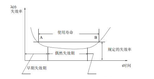
Bathtub curve
Practice has proved that the failure rate of most equipment is a function of time, and the typical failure curve is called the bathtub curve. The shape of the curve is high at both ends and low in the middle, which has obvious phases and can be divided into three stages: early failure period, accidental failure period, and severe failure period. The bathtub curve refers to the change of reliability of the product during the entire life cycle from input to scrapping. If the failure rate of a product is taken as the reliability characteristic value of the product, it is a curve with the use time as the abscissa and the failure rate as the ordinate coordinate. Because the curve is high at both ends and low in the middle, it is somewhat like a bathtub, so it is called the "bathtub curve". The failure rate varies with the use time and is divided into three stages: early failure period, accidental failure period and wear loss period.
Maintenance routine
2. Work content and relationship
1. Power-on debugging
Focus:
-
Check whether the new equipment or system can be powered on normally; Check whether the equipment or system after expansion or transformation can be powered on normally to verify the rationality of the design.
-
Check whether the repaired equipment or system can be powered on normally, and check the handling of equipment failures and hidden dangers.
-
Initial debugging configuration parameters are crucial for the stable operation of equipment or system, and improper parameter changes will cause the system to not work normally, and even damage the system.
Work Schedule:
-
Personnel involved: professional engineers (power distribution and other majors), operation and maintenance technical managers, equipment vendor engineers.
-
Personnel functions: According to the SOP of the equipment vendor, the professional engineer or the equipment vendor engineer will start the power-on. According to the SOP of the equipment vendor, the parameter debugging is carried out by professional engineers or equipment vendor engineers.
Additional Notes:
SOP: SOP is the capital letter of the three words Standard Operating Procedure, that is, the standard operating procedure, which describes the standard operating procedures and requirements of a certain event in a unified format to guide and standardize daily work.
Integrated UPS scenario power commissioning
-
Basic principles:
1. When dual input or dual power supply, it is recommended to power A first and then B to power.
2. Power on the integrated UPS, then power on the lighting and air conditioning, then power on the computer room management system, and finally power on the IT load.
-
Basic process:
1. Check before powering up
2. System power-on and debugging
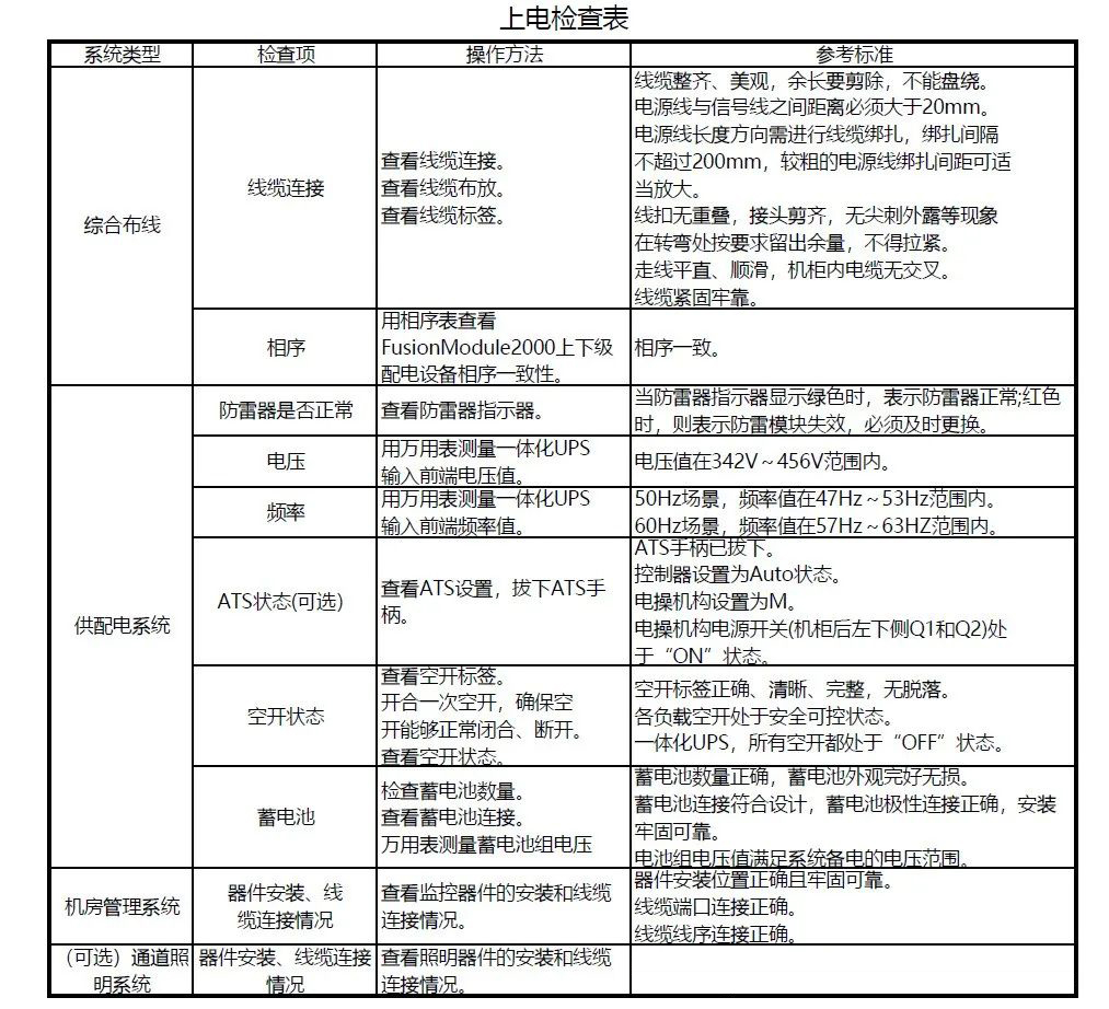
-
Procedure:
Step 1 Close the external power supply of the integrated UPS external to the mains power supply, power on the integrated UPS cabinet, the power indicator above the integrated UPS cabinet is lit, and the power on is normal.
Step 2 Close the UPS input to leave QF1 empty, wait for about 2~3 minutes, and the MDU display will start. Set the language, time, network parameters, and system parameters (single parallel, voltage frequency, battery capacity, number of units).
Step 3 Confirm that the system bypass input is normal, the system is powered by the bypass, and check the system operation status chart in the monitoring display module to confirm whether the system has been powered by the bypass. Step 2 Close the UPS input to leave QF1 empty, wait for about 2~3 minutes, and the MDU display will start.
Step 4 Turn on the inverter.
Step 5 After the inverter is turned on, the integrated UPS is powered by the inverter, and the "bypass power supply" alarm in the MDU disappears.
Step 6 Check whether the actual battery capacity is consistent with the number of cells and the value set in the monitoring interface, and use a multimeter to test whether the sum of the absolute voltage of the negative battery pack and the voltage of the positive battery pack is greater than a certain value (2× the number of battery cells) to check whether the battery pack connection is normal.
Step 7 After confirming that the battery pack is connected, close the battery pack and enter it empty.
Step 8 (Optional) Close the UPS lighting output empty to see if the AC actuator "PWR" indicator light is on. Power on the lighting.
Step 9 Close the integrated UPS cabinet air conditioner and turn on the air conditioner.
Step 10 Close the integrated UPS IT output and turn on the corresponding device.
Step 11 Check if the monitoring part is powered on normally.
-
Routine maintenance
Focus:
-
Check the integrity of the equipment's components, cleanliness, and aging.
-
Record parameters, alarms, logs and status during the daily operation of the equipment, update it in time to form a dynamic SCP, and evaluate it later.
-
Check the function and operation of the equipment through operation.
-
Regularly clean the outside and inside of the equipment.
-
Check whether there are hidden dangers in equipment, systems and the external environment.
Work Schedule:
-
Personnel involved: operation and maintenance duty officer, operation and maintenance duty leader, professional engineer, operation and maintenance technical manager, equipment supplier engineer.
-
Personnel functions: MOP written by the operation and maintenance technical manager or provided by the equipment supplier, and professional engineers or equipment vendor engineers carry out periodic maintenance and maintenance work according to the MOP; The operation and maintenance duty squad leader formulates a routine maintenance personnel plan, and the operation and maintenance duty officer conducts routine maintenance inspections according to the plan; The operation and maintenance shift leader refreshes the SCP data center and forms periodic assessment reports.
Additional Notes:
MOP: MOP is the capital letter of the three words Maintenance Operating Procedure, that is, the maintenance operation process, which formulates operating procedures for each maintenance, repair, and installation operation of key infrastructure equipment in the computer room, and some MOPs will also include SOPs. The equipment supplier can be asked to provide MOP advice, but the responsibility for the final confirmation and review of the MOP lies with the operation and maintenance team, and the responsibility for approval lies with the operation and maintenance management team.
-
System joint debugging
Focus:
-
Find out if there are any "shortcomings" in system design and equipment performance that affect the overall situation.
-
Detect whether the equipment installation is suitable for future operation and maintenance.
-
check whether the equipment installation and operation quality is stable and reliable.
Work Schedule:
Personnel involved: professional engineers (power distribution and other majors), operation and maintenance technical managers, operation and maintenance duty officers, operation and maintenance shift leaders, equipment vendor engineers.
Based on best practices in data center projects, IBM advocates a "five-step" process for joint commissioning and testing of data center infrastructure. namely
Step 1 - Drawing data review and commissioning plan formulation
Step 2 (Level 2) - Factory acceptance test
Step 3 (Level 3) - On-site inspection
Step 4 (Level 4) - Single-system acceptance test
Step 5 (Level 5) - Comprehensive system performance linkage debugging verification
The "five-step method" process is also an internationally recognized workflow specification for professional commissioning and validation of data centers:
Step 1 - Drawing data review and commissioning plan formulation
-
Debugging and verifying the structure and division of labor of the work team
-
Whether the system reflected in the drawings is "testable"
-
Whether the drawing materials have clarified the operation sequence
-
Testing verifies that the required resources (personnel, time, energy, load, instruments) are in place
-
The formulation of the commissioning master plan
Step 2 (Level 2) - Factory acceptance test
-
The performance verification of the core equipment of the power system and air conditioning system before leaving the factory
-
Rectify and correct the problems found in the test and verification at the factory
-
Avoid or reduce delays in on-site construction caused by equipment failures
-
An important sign of the acceptance of the owner's equipment procurement contract
Step 3 (Level 3) - On-site inspection
-
Check that the installation on site is consistent with the design drawings.
-
The equipment and facilities for operation and commissioning verification are ready on site.
-
Check that the power condition on site is safe and usable.
-
Check that the safety status of the site meets the requirements of operation and commissioning.
Step 4 (Level 4) - Single-system acceptance test
-
The device is powered on, and the system is started for testing.
-
Test the system function at the design load level, the air conditioning system load is not less than 30%, and the power system load is not less than the rated capacity of a single device.
-
Validate failover modes within each redundant system.
-
Validation and calibration are performed at the metering, control and data collection points of each system.
-
Record the test results and system efficiency.
Step 5 (Level 5) - Comprehensive system performance linkage debugging verification
-
Simulate the interruption of external resources such as electricity and water, and test the system response and switching mode.
-
The air conditioning system heat load simulation test, the air conditioning system load is gradually increased from 0 to 100%, and the performance of each part of the air conditioning system is verified.
-
System integration test, comprehensive test of the interface performance of multiple systems such as electrical, air conditioning, fire protection and intelligent control.
-
Carry out multi-system continuous operation (generally not less than 12 hours) test under full load to verify the stability of the system.
-
Record the test results and system efficiency.
-
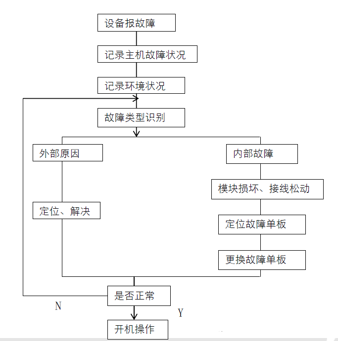
Troubleshooting
Focus:
-
Fault emergency plan, implement redundant plans, restore business as soon as possible or ensure that business is not interrupted.
-
Eliminate faults, eradicate faults and discuss root causes in administrative discussion groups, and form solutions (such as expansion, transformation, optimization, etc.).
Work Schedule:
-
Personnel involved: professional engineers (power distribution and other majors), operation and maintenance technical managers, equipment vendor engineers.
-
Personnel functions: EOP is prepared according to the operation and maintenance technical manager and equipment engineer, and the professional engineer or equipment vendor engineer conducts fault emergency plan operation according to the EOP during the failure. In the later stage, the equipment system fault removal process is carried out according to the SOP.
Additional Notes:
EOP: EOP is the capital letter of the three words Emergency Operating Procedure, that is, the emergency operation process, the operation process that needs to be carried out to start a redundant or standby system to ensure that the business is not interrupted or resume in the event of an emergency equipment or system failure.
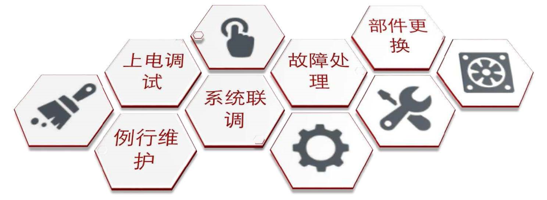
Component replacement
Focus:
-
Equipment system components that have reached their service life can be restored to normal operation by replacing them.
-
Equipment system components with hidden dangers and failures can be restored to normal operation by replacing them.
Work Schedule:
-
Personnel involved: professional engineers (power distribution and other majors), operation and maintenance technical managers, equipment vendor engineers.
-
Personnel functions: Replace equipment system components according to the operation and maintenance technical manager and equipment engineer according to SOP.
Replace the integrated distribution cabinet & precision distribution cabinet MCB
Procedure:
Step 1 Open the front door of the distribution cabinet, switch the input and output switches of the distribution cabinet to the OFF state, and the upper and lower switches are also disconnected.
Step 2 Remove the screws on the panel of the distribution cabinet and leave it for later use, and remove the panel.
Step 3 Disassemble the cables on the left and right ends of the MCB.
Step 4 Use a flathead screwdriver to push the MCB black snap fastener outward as shown, and then disassemble the MCB in the direction of the inside of the distribution cabinet.
Step 5 Install the new MCB.
Step 6 Connect the cables. The recommended terminal holes for MCB cables are shown below.
Step 7 Reassemble the panel back into the distribution cabinet.
Come to an end.


