


Large commercial, hotel, office, hospital and commercial complex buildings are usually equipped with a large number of ventilation, air conditioning, heating and cooling sources, water pumps, electrical lighting, elevators and other equipment. To achieve convenient and effective control of these equipment, a building automation system, also known as a BAS (Building Automation System) or BA system, is usually installed.
Normally, the BAS system architecture is on a communication network, and the communication network architecture is set up at a hierarchical level.
1: BAS system architecture
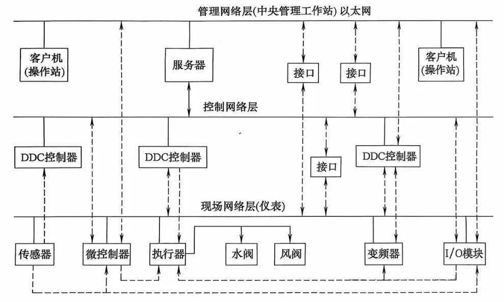
Normally, the network architecture can coordinate with each other between the process control levels in the horizontal direction, and can also transmit data in the vertical direction, send and receive instructions, and exchange data between the horizontal levels.
This control system generally decentralizes the control functions as much as possible (the number of devices controlled by a single DDC/PLC controller should not be too large), and the management functions are as centralized as possible. The main purpose of decentralized control is to disperse risks, improve the reliability of the control system, and will not affect the normal operation of building mechanical and electrical equipment due to the failure of the local controller.
1 Management level
Management is the monitoring computer, which is customarily called the upper computer.
The monitoring computer includes servers and workstations, and the server and workstation software are usually installed on multiple PCs, and a LAN system is established with multiple clients (operating stations) working in parallel. When the system is small, it can also be installed on a single computer.
Monitoring computers generally use industrial computers or office computers that are compatible with the processing performance of the system.
The central monitoring host completes the monitoring, control and management of all air conditioning equipment by communicating with the DDC field controller. Automatically record, store and query historical operation data, timely alarm and automatic recording of equipment faults and abnormal parameters, etc.
2 Control level
The field control layer is mainly the field DDC controller or PLC controller, which adopts Ethernet networking and TCP/IP communication protocol.
In civil buildings, DDC controllers are generally used, which are directly connected with on-site sensors, actuators and transmitters to complete real-time monitoring of on-site equipment and complete information exchange with upper-level computers through communication networks.
DDC field controllers are customarily referred to as subordinates. In addition to receiving commands transmitted by the host computer, it can also transmit the local data and status to the host computer, when there is no intervention from the host computer, the DDC field controller can control the equipment individually, and use the set parameters for various algorithm operations to achieve output control.
The DDC controller is set according to the system of the equipment, that is, the measurement control point of the same system is connected to the same on-site DDC controller to increase the reliability of the system and facilitate system debugging. The input and output points of the on-site DDC controller should have an appropriate margin for system adjustment and future expansion, and the general reservation should be more than 10% (some commercial management companies require not less than 30%).
The control network layer can include multiple communication buses working in parallel, each of which can be connected to the management network layer (central management workstation) through the network communication interface, or directly connected to the server through the RS485 communication interface of the management network layer server or the built-in communication network card.
3 Site level
The field network layer consists of a communication bus connecting a microcontroller, an intelligent field input and output module, an intelligent field instrument (intelligent sensor, intelligent actuator, intelligent frequency converter, etc.), and an ordinary field instrument, and the communication bus can be Ethernet (LAN communication protocol) or a fieldbus.
(Normally, ordinary field instruments, including sensors, power transmitters, illuminance transmitters, actuators, water valves, dampers, and frequency converters, cannot be directly connected to the communication bus.) )
1) Microcontroller
A microcontroller is a specialized controller for use on end-of-building devices embedded with computer hardware and software, and is an embedded system.
Different types of control devices use different types of microcontrollers, and different types of microcontrollers can be connected to the same communication bus.
Microcontrollers complete all control application operations independently of DDC controllers and central management workstations, and usually have standard control functions determined by certain international industry standards (such as standardized control of common functions at the end of air conditioners, without reprogramming for a certain project), so as to meet the needs of control application standardization and data communication standardization, so that the products are interoperable and establish an open system.
The microcontroller in the HVAC system is the "brain" of the HVAC system, capable of receiving signals from various sensors and controlling the working status of various components of the air conditioner, such as compressors, fans, valves, etc., according to preset programs and algorithms, so as to achieve precise adjustment of indoor temperature, humidity, air quality and other environmental parameters.
Microcontrollers are usually installed directly in the control cabinet of the controlled equipment and become part of the building equipment, such as the air handling unit microcontroller, that is, installed in the control cabinet that comes with the unit.
2) Intelligent field instrumentation
Intelligent field instrument is a networked field equipment embedded in computer hardware and software, with microcomputer (microcomputer) as the main body, through the communication bus to communicate with controllers and microcontrollers, such as heat meters and flow meters with remote transmission functions.
(The difference between microcontrollers and microcontrollers is that they have different application scenarios, microcontrollers pay more attention to the control ability of external devices, realize system automation, and have a higher price; The microcontroller focuses more on the integration of computing, collects data and processes it and then sends it out, with simple functions and good economy)
3) Ordinary field instrumentation
Ordinary field instruments are non-intelligent devices, which can only be connected end-to-end with controllers, microcontrollers, and (I/O) modules, and directly transmit analog and digital signals between them.
4) Distributed input/output (I/O) module
Distributed input/output module (hereinafter referred to as I/O module) is a kind of equipment used in many fields such as building intelligence and industrial automation. Its main function is to collect various input signals (such as sensor signals, including temperature, pressure, liquid level, flow sensors, etc., as well as switching volume signals, such as buttons, limit switches, etc.), and convert these signals into digital signals, which are transmitted to the central control system (such as programmable logic controller PLC, direct digital controller DDC, etc.) through the communication network.
At the same time, it can also receive the output signal from the central control system and convert it into appropriate physical quantities (such as controlling the actions of actuators such as relays, valves, motors, etc.), so as to realize remote control of field equipment.
A distributed (I/O) module is a networked field device embedded in computer hardware and software, which is connected to the controller computer module through a communication bus as an integral part of the controller.
When forming a BAS, it is often necessary to integrate the inputs and outputs of the process into the system. If the (I/O) module data node is far from the programmable controller, it will require long cables, which is difficult to implement and may reduce reliability due to electromagnetic interference.
Distributed (I/O) modules are ideal solutions for such systems, where the control CPU is centrally located and the (I/O) devices operate locally and smoothly, while the Modbus RTU communication protocol ensures stable and smooth communication between the control CPU and the I/O devices.
(Note: Modbus RTU: is a simple serial communication protocol, the data format is relatively simple, mainly focusing on the transmission of data and the basic interaction between devices, and its message structure is composed of address field, function code field, data domain and check field, etc.) The protocol is simple and open, and many devices from different manufacturers support this protocol, and when integrating the system, it is easy to connect devices of different brands to achieve communication between devices, and the system integration is relatively easy and the cost is low. )
Distributed input/output (I/O) modules are often used for communication between small systems and simple devices, such as connecting sensors, actuators, frequency converters and other equipment with higher-level control systems, realizing basic data acquisition and control functions, and are widely used in industrial automation, energy management, building intelligence and other fields.
2. Communication network
The monitoring computer (upper computer) and the DDC field controller (lower computer) are in different communication networks, and the network where the former is located is called the management network, which is generally Ethernet. The network in which the latter resides is called the control network, and the control network is also called the control bus. Because of the low cost, the RS485 bus is commonly used in the current building control.
The control network and management network adopt completely different communication protocols and standards, so they cannot be directly interconnected, and the network controller needs to be used for protocol conversion to realize the interconnection communication between the two, generally using TCP/IP, BACnet or Modbus protocol.
The communication distance of RS485 can reach 1200m, and generally only requires two wires, and the main control device and multiple slave devices are connected hand-in-hand. However, it has the following disadvantages:
1) RS485 adopts half-duplex mode, and only data can be sent or received at the same time, not at the same time, resulting in relatively low data transmission efficiency.
2) The communication capacity of the RS485 bus is small, and theoretically only allows a maximum of 32 devices to be connected to each section, which is not suitable for the multi-user capacity requirements of buildings as nodes.
3) The communication rate of the RS485 bus is low, the transmission rate is inversely proportional to the transmission distance, at the transmission rate of 100Kbps, the maximum communication distance can be reached, if you need to transmit a longer distance, you need to add a 485 repeater.
4) RS485 bus usually does not have isolation, when a node on the network fails, it will lead to the whole or partial paralysis of the system, and it is difficult to judge its fault location.
5) The RS485 bus adopts the host polling method, which will cause the communication throughput to be low, which is not suitable for the occasion of large communication volume requirements (or low average communication volume, but bursty), when the system is large, the real-time performance is poor.
The host constantly polls each slave, and each slave must analyze all the queries of the host to decide whether to respond to the host.
Ethernet architecture form
Another network architecture of BAS is that both the management domain network and the control network use Ethernet, which has developed rapidly in recent years due to some unique advantages.
When the number of controlled HVAC equipment is large, the traditional bus building control system is difficult to meet its technical requirements such as speed and capacity, and can use Ethernet structure. Its advantages are:
1) The building control system can directly use the integrated wiring system in the building, so as to simplify the network structure of the building control system and reduce costs.
All one-to-one air conditioning communication between DDC and DDC, DDC and central station adopts Peertopeer communication mode, and does not need to use master/slave communication mode.
2) This Ethernet network structure can not only simplify the network structure and reduce the cabling workload, Ethernet has the advantage of high transmission rate, but also improves the communication rate between DDCs.
The field controller DDC connected to the network can be assigned a real and valid IP address, such a field controller DDC is also known as IP DDC controller or Ethernet DDC controller, which is equivalent to each 485 network DDC controller has a built-in NCU network controller (a device specially designed to control and manage network communication).
3) This form of network structure Ethernet is based on TCP/IP protocol, in addition to the central station, the field controller DDC also adopts TCP/IP protocol, so that the building control system can be connected to Imternet more smoothly, with excellent remote monitoring performance.
4. The building control system no longer needs to introduce a network controller as a bridge between the central management workstation and the field controller DDC, which is connected directly to the Ethernet switch through an unshielded twisted pair cable (UTP) with RJ45 interface; However, the sensors and actuators are still directly connected to the field controller DDC, the same as fieldbus-based building control systems.
5. This Ethernet network structure solves the problem that multiple fieldbus technologies and standards coexist and are not compatible with each other, which is conducive to the standardization and generalization of the building control system.
3. Communication protocols
Communication protocols used by different types of networks often vary.
The communication protocol used by Ethernet is called Transmission Control/Internet Protocol (TCP/IP,TransferControlProtocolIntermetProtocol)。 There are many kinds of communication in the control network, and they are related to the products of control equipment manufacturers, and the international standard protocols include TCP/P, BACnet, LonTalk, MeterBus and ModBus.
In order to enable devices from different manufacturers to communicate with each other and operate on the basis of mutual communication, a communication protocol developed by the American Society of Heating, Refrigerating and Air-Conditioning Engineers (ASHRAE) for building automation and control networks BACnet (ADataCommunication ProtocolForBuildingAutmationandControlNetwork), It has been widely accepted by the industry and has become the mainstream communication protocol for intelligent buildings in the world.
4. An example of a BAS system in a commercial complex project
1. Overview
The project is equipped with a building automatic control system in the commercial area, and the system is connected to the intelligent private network.
2. Monitoring scope
HVAC: air conditioning system, fresh air system, air curtain, heating system, air supply and exhaust system, etc., are controlled by BAS.
Water supply: The alternating frequency feed pump, domestic water tank, etc. in the domestic water pump room are self-contained in the water supply equipment, and the BAS only monitors and does not control.
Drainage: Mainly basement sumps, sewage pumps, etc., drainage equipment is a self-contained system, and BAS is only supervised and not controlled.
Chillers, transformers and distributors, elevators, direct combustion units, gas boiler systems, multi-line systems, and air-cooled heat pump systems are all provided by equipment manufacturers with standard communication interfaces and connected to BAS through gateways.
3. The specific monitoring content of each main equipment
1) Air conditioning unit monitoring content
Monitor the operating status, trip alarm, and automatic status of the blower, and control the start-stop and frequency converter fault alarm, adjustment and feedback. fresh air temperature and humidity, supply air temperature and humidity, return air temperature and humidity; air supply pressure; anti-freeze alarm; Hot and cold water valve control; humidifier valve control; filter over-resistance alarm to remind operation management personnel to clean the filter in time; According to the comparison of the temperature and humidity of fresh air, supply air and return air with the set value, as well as the carbon dioxide concentration and PM2.5 concentration of the return air, adjust the damper valve, water valve and humidification valve to meet the requirements of the indoor environment. The damper is interlocked with the blower, and the fan is automatically shut off when it stops. The software is used to measure the time, the number of starts, the running time is displayed, and the equipment is automatically prompted to be repaired regularly. The central station displays and records the status, alarm information, operating time, and historical parameter information of the fresh air unit with color graphics, which can be output by printer.
2) Fresh air unit monitoring content
fresh air temperature and humidity, supply air temperature and humidity; blower operating status, fault alarm; blower hand/automatic changeover; blower start/stop control; fault alarm, adjustment and feedback of frequency converter; anti-freeze alarm; filter blockage alarm; Hot and cold water valve control;
humidifier valve control; Damper switch control control content: blower start and stop and electric adjustment of the opening of the water valve, damper and humidification valve according to the fresh air temperature and humidity, supply air temperature and humidity control to meet the best balance of indoor environment and energy saving; 3) Monitoring content of the air supply and exhaust system monitoring the operation of the air supply and exhaust system; monitoring content; fan operating status; fan fault alarm; fan hand automatic status; fan start-stop control;
4) Sewage system monitoring content
monitoring the operation of the sewage system; monitoring content; the operating status of the sewage pump; sewage pump failure alarm; Sump level monitoring.
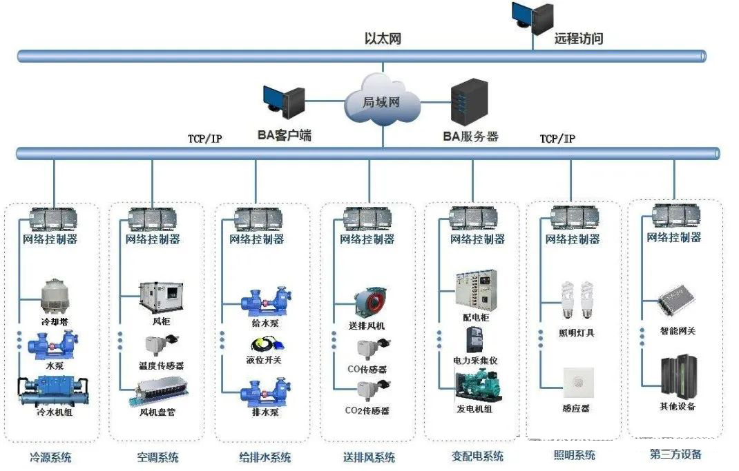
3) System architecture
The building automation system of this project adopts a network structure mode, which should adopt a centralized management and distributed control system, and adopt a three-layer network architecture with a hierarchical topology.
Management: It is composed of a building automation system server and a workstation, and the system server communicates with the network controller through the TCP/IP network protocol, and the management equipment can also be integrated with the independent monitoring subsystem of third-party equipment through other network interfaces.
Monitoring layer: It is composed of direct digital controllers (DDC) set up at each layer, and the field controllers communicate through the communication bus, and are connected to the management layer through the network controller. At the same time, the direct digital controller can operate independently and automatically operate according to a pre-programmed program even if the local network connection is interrupted.
Field equipment layer: It is composed of various sensors and actuators installed on the controlled electromechanical equipment, and realizes the monitoring function of electromechanical equipment through the input and output monitoring points of the direct on-site digital controller.
Each air-conditioning room is equipped with an independent DDC control box, and each air-conditioning unit should be controlled by an independent DDC controller. Each network controller has at least 30% of the number of nodes allowed.
4. Center configuration
BAS automatic control equipment is set up in the commercial fire control room, and the automatic control of the mechanical and electrical equipment of the project is completed by setting up the building automatic control system software and workstation in the fire control center.
5. Energy consumption monitoring system
It is mainly for the remote reading and measurement construction of smart meters and water meters in independent districts and cities in shopping malls.
The data collection of this system mainly includes a signal collector: the signal collector is used to collect and manage communication of the terminal intelligent meter in groups, and provides working power for the terminal meter.
The system workstation collects various data of terminal intelligent water meters, smart meters and intelligent cooling and heat meters through the signal collector, realizes real-time detection of billing data, gun testing of system equipment status, and saves the data in the local system database, which can carry out data statistics, analysis, processing and report printing at any time, and the energy consumption blue test system can be connected to the management platform of the commercial management company in the later stage.
5. Summary
For mechanical and electrical majors (HVAC, electrical, water supply and drainage), building automation systems are not only intelligent majors, but also closely related majors.
In engineering design, HVAC, water supply and drainage, and electrical professional air conditioning, water pumps, elevators and other equipment need to be connected to the BAS system, according to the requirements of intelligent majors, the equipment needs to come with its own communication interface and supported communication protocols.
For example, the device is required to have an RS485 communication interface and support BACnet or Modbus communication protocols.
For example, the control of each air conditioning equipment and each set of air conditioning system and HVAC major need to think clearly and clarify various control requirements, control principles or control logic and control purposes to be achieved in the design process


