


With the development and application of cloud computing, big data, artificial intelligence and other technologies, the computing volume of data centers and related equipment as information infrastructure is increasing, and the processing capacity and integration of data center servers and communication equipment are constantly improving. Due to the limitations of physical space and low specific heat capacity of air, air-cooled technology is difficult to meet the heat dissipation load requirements of high-power components, as shown in Figure 1.
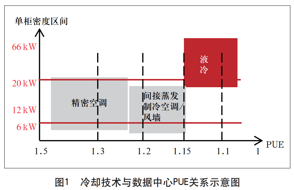
At the same time, the national level continues to promote the requirements of green and low-carbon construction of data centers, and the "Action Plan for Green and Low-carbon Development of the Information and Communications Industry (2022-2025)" jointly issued by the Ministry of Industry and Information Technology and other seven ministries and commissions clearly mentions that by 2025, the energy utilization efficiency (PUE) of new large-scale and ultra-large data centers across the country will be reduced to less than 1.3. The cooling capacity of liquid is 1000~3000 times that of air, and liquid cooling technology has become an effective means to reduce PUE in data centers with its efficient heat dissipation ability.
To sum up, under the necessary premise of introducing liquid cooling technology into data center construction, it is necessary to consider the new challenges posed by the introduction of liquid cooling technology to the integration and construction of data center hardware systems. This article will focus on the technical routes of cold plate, immersion and spray liquid cooling, focus on the technical requirements of data center hardware system integration in cold plate liquid cooling scenarios, and propose data center hardware system integration schemes in cold plate liquid cooling scenarios.
1. Liquid cooling technology
Liquid cooling technology is a liquid as a refrigerant, using liquid flow to transfer the heat generated by the internal components of the data center ICT equipment to the outside of the equipment, so that the heating parts of the ICT equipment can be cooled, so as to ensure the safe operation of the ICT equipment. According to different contact methods, liquid cooling technology can be divided into indirect contact liquid cooling (cold plate liquid cooling) and direct contact liquid cooling (immersion liquid cooling and spray liquid cooling).
1.1 Indirect contact liquid cooling technology
Indirect contact liquid cooling is mainly based on cold plate liquid cooling technology, which fixes the liquid-cooled cold plate on the main heating device of the ICT equipment, and there is no direct contact between the heat source and the coolant of the ICT equipment, and the heat is taken away through the liquid flow through the cold plate, so as to dissipate heat.
The logical architecture of cold plate liquid cooling technology is shown in Figure 2. Its main components are as follows.
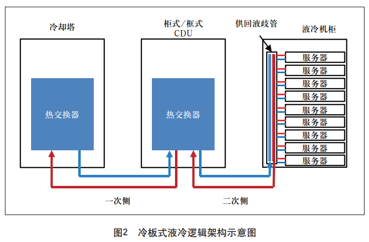
Cooling towers refer to equipment that disperse heat generated by liquid circuits into outdoor air, generally placed outdoors. Liquid-cooled distribution unit (CDU) refers to the distribution of cooling liquid flow to liquid-cooled electronic equipment, which mainly has two physical forms, namely cabinet-type CDU (externally placed in the fully liquid-cooled cabinet) and frame-type CDU (built-in fully liquid-cooled cabinet). Liquid cooled cabinet refers to a device used to cool the inflow and outflow of liquids and to cool electronic equipment. The primary side is also called the primary pipeline, which refers to the circulating water system connecting the cooling tower to the liquid-cooled distribution unit and the liquid-cooled cabinet. The secondary side, also known as the secondary pipeline, is used to connect the liquid-cooled distribution unit to the cooling circulating water system of the liquid-cooled components (in the liquid-cooled cabinet). Among them, the supply and return manifold, as one of the key components in the secondary side circuit, can distribute the cooling fluid flowing into or out of the equipment in the liquid cooling frame.
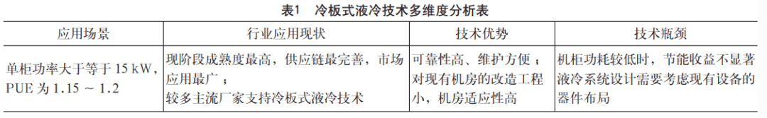
The cold plate liquid cooling technology is analyzed from many aspects such as application scenarios, industry application status, and the advantages and disadvantages of the technology itself, and the specific analysis results are shown in Table 1.
1.2 Direct contact liquid cooling technology
Direct contact liquid cooling technology refers to the cooling method of direct contact between the heating components of electronic equipment and the coolant, mainly including two technical routes: immersion liquid cooling and spray liquid cooling.
Immersion liquid cooling refers to the direct contact between the heating device and the cooling liquid by immersing the heating device of the electronic device, and cooling it through heat exchange. The main equipment and facilities involved include outdoor cooling sources, cooling subsystems, liquid cooling lines, and immersion cavities (liquid-cooled chassis). Immersion liquid cooling can be divided into two types: single-phase immersion liquid cooling and phase change immersion liquid cooling according to whether there is a phase change in the medium.
The principle of single-phase immersion liquid cooling is to absorb heat from the direct contact of the heat load of electronic equipment through the coolant in the submerged cavity subsystem, and the heated coolant transfers the heat to the primary cooling medium under the action of the circulation pump and heat exchanger in the cooling subsystem, and finally releases the heat to the outdoor environment through the outdoor cooling source.
The principle of two-phase immersion liquid cooling is to absorb heat from the coolant cooling in the submersion chamber subsystem to the heat load of electronic equipment in direct contact phase change, and the gaseous refrigerant after the phase change and the condenser in the submersion chamber exchange heat, transfer the heat to the cooling medium and become a liquid, the liquid flows back to the cavity under the action of gravity, and the cooling medium absorbing the heat is released into the outdoor environment through the outdoor cooling source equipment.
Spray liquid cooling technology refers to spraying coolant on heated electronic devices by storing liquid and opening holes on the top of the chassis to achieve the purpose of cooling. The main equipment and facilities involved include outdoor cooling modules, cooling distribution units, liquid cooling pipelines, spray liquid cooler cabinets (inlet tank and return tank), etc. The spray liquid cooling will be transported to the inside of the sprayer cabinet by the coolant pump after cooling in the cooling distribution unit; After the coolant enters the cabinet, it directly enters the liquid distribution device corresponding to the equipment through the dispenser for spraying; The coolant is sprayed and cooled through the heating device in the electronic equipment or the thermal conductive material connected to it; The heated coolant is collected through the return tank and pumped to the cooling distribution unit for the next refrigeration cycle.
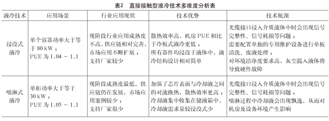
For immersion liquid cooling technology and spray liquid cooling technology, multi-dimensional analysis is carried out from the application scenarios, industry application status and advantages and disadvantages of the technology itself, and the specific analysis results are shown in Table 2.
2. Traditional data center hardware system integration scheme
The integration of hardware systems in traditional data centers mainly completes the planning, integration implementation, and joint commissioning and delivery of hardware layer multi-manufacturer and multi-type equipment in engineering projects, which is the extension and implementation of engineering design and provides the necessary hardware system environment for the implementation of software system integration. The workflow of traditional data center hardware system integration is shown in Figure 3.
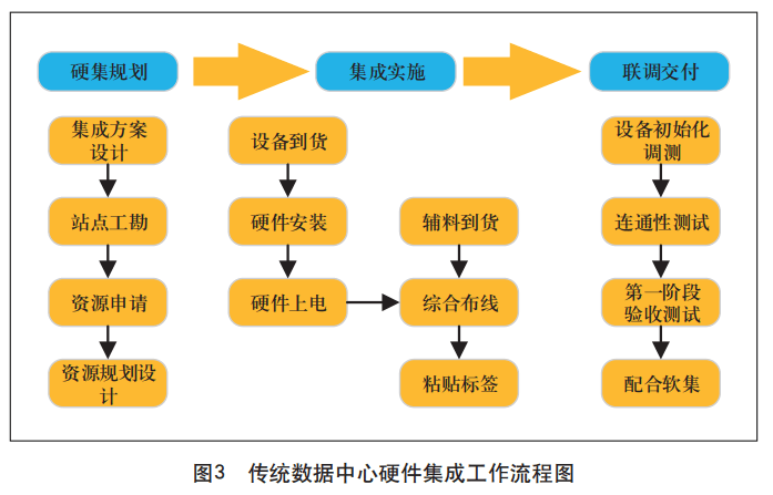
The key work links in the traditional data center hardware integration scheme are described as follows.
Integrated scheme design. Planning and design of data center hardware networking topology, cabinet layout, power distribution, physical connection information, server configuration information, switch port configuration information, routing configuration information, security equipment configuration information, and equipment management information.
Site engineering survey. The survey includes the computer room environment, cabinet layout, rack power, bridge routing, power supply method and cooling method. According to the survey results, according to the engineering division interface, make a clear procurement plan for the length, color and other specifications of materials required for the project, such as cables, and formulate a clear procurement plan for the auxiliary materials required for the necessary transformation in the computer room.
Auxiliary materials are provided. According to the design drawings and division of labor interface, the corresponding responsible unit will provide relevant auxiliary materials. Auxiliary materials mainly include cables and necessary auxiliary materials required for engineering construction, such as cable ties, reinforced trays, L brackets, cold-pressed terminals, Velcro, fiber optic sleeves, winding cylinders, lower fiber grooves, industrial connectors, labels, copper noses, winding pipes, terminal posts, cable management frames and insulation cotton, etc.
Hardware installation supervision. Supervise the installation and power-up of all main equipment of the data center engineering construction project, supervise the completion of all cable deployment and interconnection, and complete the corresponding network interconnection configuration. The installation of equipment and supporting materials must comply with relevant process standards and requirements.
Device initialization and commissioning. Complete the basic configuration and commissioning of all hardware devices, such as server BMC, RAID, BIOS, etc., hardware management access switches, management core switches, etc., and complete hardware management network interoperability.
Connectivity testing. All hardware equipment in the data center engineering construction project are configured and checked according to the integrated design scheme, and the connection and interoperability tests of power supply and physical cables are completed according to the design, and the hardware management IP addresses of all equipment are confirmed.
Partnering with software integrators. Cooperate with software integrators to complete various equipment networking and business function analysis involved in the technical solution. Cooperate with the deployment and debugging of software and hardware systems, adjust the changes in resource requirements such as computing, network and storage generated during the software integration process, and assist software integrators in defining, coordinating and managing problems between software and hardware manufacturers.
3. Liquid-cooled data center hardware system integration technical solution
The data center hardware system integration scheme in the liquid cooling scenario should be adjusted and adapted to the technical characteristics of the liquid cooling data center in the integration planning, integration implementation and joint commissioning delivery stages on the basis of referring to the traditional data center hardware system integration process to meet the requirements of liquid cooling data center engineering. The following will take the most mature and widely used cold plate liquid cooling technology solution as an example to analyze the key links of liquid cooling data center hardware system integration.
3.1 Site survey stage
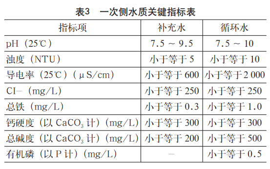
Under normal circumstances, the installation of equipment and pipelines on the primary side of the liquid cooling system is responsible for infrastructure or mechanical and electrical majors, and is not within the scope of data center hardware system integration. However, because the CDU needs to be docked with the primary side pipeline, it is necessary to pay attention to the primary side circulation water quality during the site survey process, and the quality of the primary side circulation water directly affects the heat transfer efficiency and service life of the CDU. In order to support the long-term stable operation of the liquid cooling system, the key indicators of water quality of the CDU primary closed circulating water system are shown in Table 3.
3.2 Equipment arrival stage
In order to ensure the airtightness of the liquid cooling system, liquid cooling cabinets, servers, switches and other equipment will generally fill the liquid cooling pipeline with holding gas when leaving the factory. After the equipment arrives, in addition to routine inspection, first of all, the integrity of the liquid cooling pipeline should be focused, and if possible, the pressure value of the holding gas in the liquid cooling pipeline can be sampled to see if the pressure value is normal; Secondly, when handling equipment, while complying with the relevant rules and regulations of safe construction, attention should be paid to the protection of pressure-bearing pipelines.
3.3 Hardware installation stage
3.3.1 CDU and secondary side pipeline installation
The secondary side pipeline connects the CDU and the cold plate of the end equipment, and there are two general connection methods: direct connection and ring pipeline connection. The annular pipeline is a key component in the secondary side loop, which is used to connect the secondary side of the CDU and the rack manifold to achieve uniform distribution of cooling working fluid; The annular pipe network includes liquid supply ring pipe, liquid return ring pipe, CDU branch, rack manifold branch, exhaust device and liquid discharge port, etc., which are used to form a circular closed loop for the liquid supply ring pipe and the return ring pipe respectively, and to improve the flow uniformity of the annular closed loop system. In addition, there is no dead end in the ring pipe network, and the liquid is always in a flowing state and is not easy to deteriorate.
Each CDU branch and rack branch are equipped with valves connecting the CDU and the rack manifold to facilitate the maintenance of individual equipment. In order to ensure that other pipe sections can operate normally and supply liquid uninterrupted when the local pipe section is overhauled or fails, valves should be used to divide the ring pipe network into several independent sections.
3.3.2 Inspection before installation of the main equipment
Before the installation of the main equipment, it is necessary to check the airtightness of the CDU and the secondary side pipeline for leakage detection and intervention. The primary way to reduce leaks is to adopt robust leak prevention strategies. At the same time, in the actual equipment installation operation, it is necessary to formulate a complete leak management plan, which includes leak detection and intervention, and needs to meet the facility operation requirements of the data center.
In the secondary cooling circuit, it is necessary to detect at different locations where there is a risk of leakage, such as CDU, rack, quick change connectors, computing nodes, etc., and indirect detection methods can be used to detect and identify small pressure drops or flow changes in the pipeline that match the leakage characteristics by monitoring and analyzing the status of existing hardware and sensors. Direct detection methods deploy dedicated leak detection hardware in high-risk areas. A typical direct detection device is a point detector, a thin film detection tape, or a leak detection cable that records and alerts when it comes into contact with a leaking conductive coolant. For reliable leak detection, the sensor should be placed under the area where the cooling fluid is in direct contact with or may accumulate and re-contact in the event of a leak, such as racks, CDUs, secondary side loop pipes, etc., to detect potential leakage risks between the secondary side loop lines and the rack or during the cooling fluid delivery.
3.3.3 Main equipment installation
The installation of equipment such as servers and switches needs to be organized according to engineering design drawings and integration plans. Before the equipment is installed, it is necessary to do a good job of protecting the finished products inside the computer room to avoid damage to the computer room environment. Equipment installation should complete the equipment outbound and unpacking processes in advance, organize construction personnel to conduct technical training, and cooperate with equipment manufacturers to provide equipment installation guidance to avoid equipment damage caused by wrong equipment installation methods.
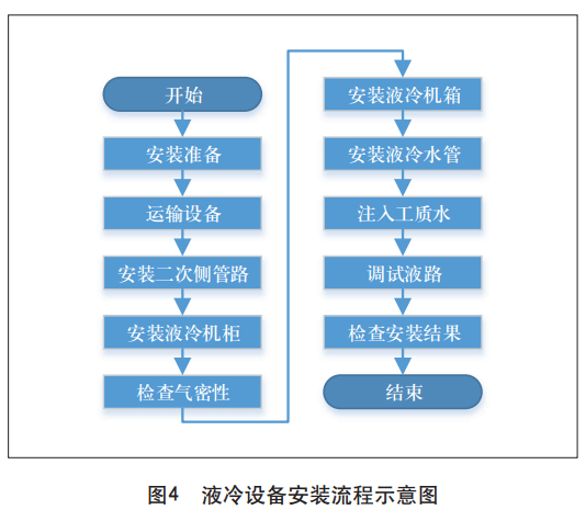
For the installation of liquid cooling equipment and cabinets using cold plate cooling, the process is shown in Figure 4.
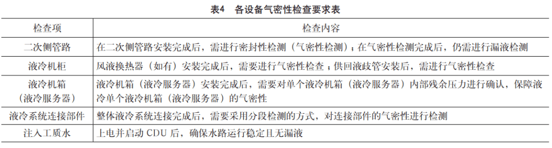
During the installation of equipment, the focus is on air tightness inspection, and the inspection content of each equipment is shown in Table 4.
3.3.4 Label pasting
After the completion of equipment installation and comprehensive wiring, in addition to the routine labeling of equipment and cables and other components, attention should also be paid to the labeling of liquid cooling pipelines. In the process of label production and pasting, the color, size, content, format and pasting position of the label must meet the relevant requirements of the engineering construction project.
3.4 Integration and commissioning stage
After the installation of the main equipment and liquid cooling system is completed, the installed equipment/system needs to be integrated and debugged. In addition to the basic commissioning of network, server, storage and security equipment, it is also necessary to carry out integrated commissioning of liquid cooling systems, mainly to complete the commissioning of CDU equipment. The main contents of CDU device commissioning include login parameter setting, solenoid/sensor control policy setting, and alarm setting.
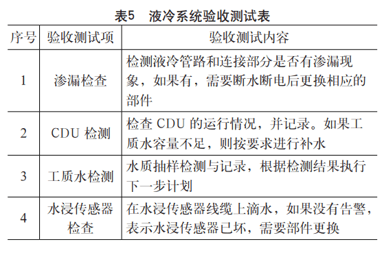
3.5 Acceptance test stage
After the integration test work is completed and all test items meet the test standards, the acceptance of hardware integration can be organized. The whole acceptance process should refer to the requirements of the acceptance specification, covering the computer room environment, hardware installation process inspection, equipment configuration, connectivity and robustness, security, etc. For the hardware integration system of liquid-cooled data centers, the acceptance test content that needs to be paid attention to is shown in Table 5.
4. Conclusion
China's "dual carbon" goal puts forward higher energy consumption requirements for data center development. The liquid cooling industry is also constantly improving the industrial chain, improving the versatility and availability of raw materials and accessories, and reducing costs. In order to actively respond to the new requirements put forward by the construction of liquid-cooled data centers, the hardware system integration of liquid-cooled data centers urgently needs to be updated and adapted, and a standard and executable hardware system integration operation mode is formed for different liquid-cooled technical solutions, so as to promote the high-quality development of liquid-cooled data center hardware system integration.


